EMC IEC Levels of Protection
EMC issues are caused by high frequency noise (voltages) from unknown sources. The EMC issue will always have at least one (1) source (radiation, coupling or conduction) and at least one (1) victim (equipment). The noise can be permanent, temporary or at random intervells such as lightning.
EMC issues are some of the hardest power quality problems to locate as well as finding perminate solutions for.
EMC Wish List For a Facility Manager
- Facility – Free of all electrical shock hazards for personnel and equipment
- Facility - Clean of electrical noise
- Facility - Quiet of electrical disturbances
- Facility - Protected against all electrical disturbances
IEC 6100-4-16 and IEC 6100-4-6 Noise Level Chart 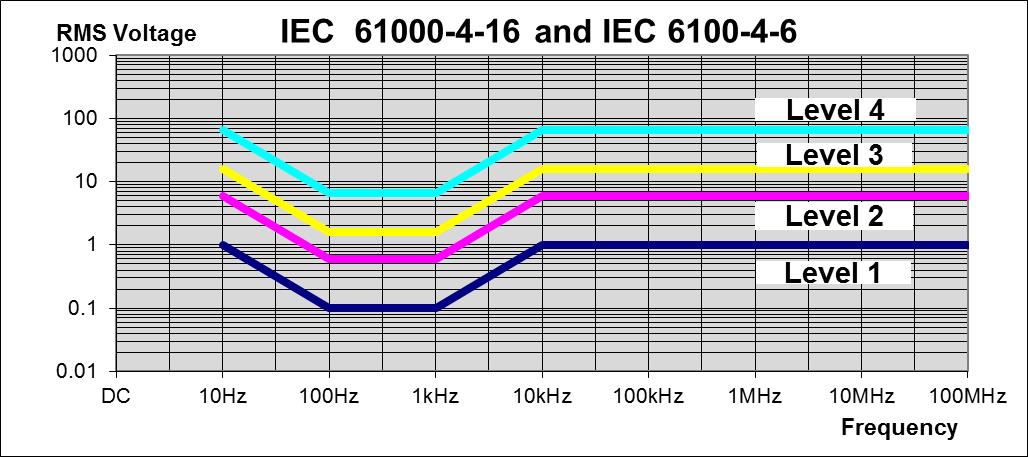
Level 1 Well Protected Equipment
- A computer room may be representative of this environment
- The installation is characterized by the following attributes: separation of the internal power supply network from the mains network
- Example: by dedicated isolation transformers; electronic equipment earthed to a dedicated earthing collector, connected to the earthing system (ground network) of the installation
- Depending on the frequency Level 1 is 1 peak volt or less
Level 2 Protected Environment
- Control room or terminal room located in a dedicated building of industrial plants and power plants may be representative of this environment
- The installation is characterized by the following attributes:
- Direct connection to the low voltage mains network; electronic equipment earthed to the earthing system of the installation
- Depending on the frequency Level 2 is 1-5 peak volts
Level 3 Typical Industrial Environment
- Industrial installations and power plants may be representative of this environment.
- The installation is characterized by the following attributes:
- Direct connection to the low voltage or medium voltage mains network; electronic equipment earthed to the earthing system of the installation (ground network)
- Use of power convertors injecting stray currents into the ground network
- Depending on the frequency Level 3 is 5-7.5 peak volts
Level 4 Severe Industrial Environment
- Gas Insulated Switchgear (GIS) and open-air High Voltage (HV) substations, and the related power plant, may be representative of this environment.
- The installation is characterized by the following attributes:
- Direct connection to the low voltage or medium voltage mains network; electronic equipment connected to the earthing system of the installation (ground network) common to HV equipment and systems
- Use of power convertors injecting stray currents into the ground network
- Depending on the frequency Level 4 is 7.5-10 peak volts
Level 5 Special Situations
- Special Situations conditions may be:
- Analyzed or investigated, and consequently immunity requirements may be higher or lower than specified for the different class may be defined
- Level 5 is 10+ peak volts
Zero Method (ZM) Noise Level Chart
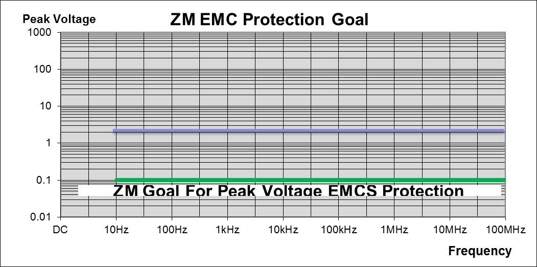
Zero Method (ZM) of locating and finding solutions for EMC issues
The Zero Method (ZM) uses six (6) reference points in the facility to measure voltage and current readings between these points to determine the points of noise that must be eliminated
- Electronic equipment reference point
- Communication equipment reference point
- Direct current reference point
- Alternating current reference point
- Grounding system reference point
- Earth reference point
- After readings are taken and the study of the trouble points are analyzed a design is developed to correct the noise issues
- ZM uses patented components (Filters, Capacitors, and Magnet Blocks) to reduce the noise levels at either the facility or the area of concern within the facility to as close to zero volts as possible
« Back to Blog
Safety Protection Grid Solutions
P.O. Box 1366
Mansfield, OH 44901
(855) 887-8463
![]()
![]()


Comments